
LED Lighting Accessories
-
Voltage Distributor with WiringRegular price From $3.32Unit price / perRegular priceSale price From $3.32
-
LED Lighting Power Supply (no wiring)Regular price From $10.63Unit price / perRegular priceSale price From $10.63

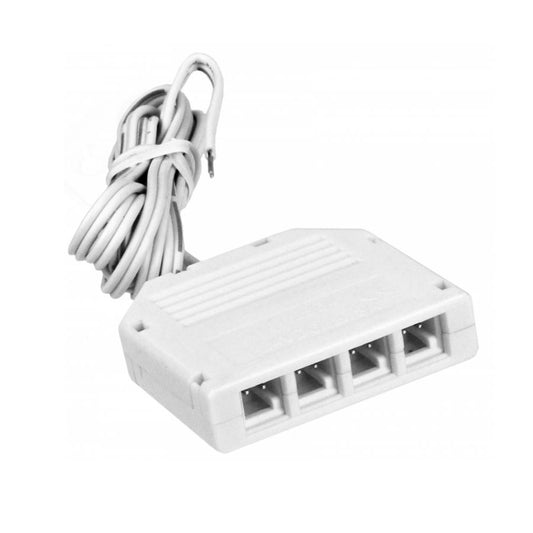

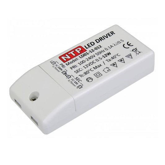
Cabinet LED lighting accessoriesinclude all electronic, electromechanical, and mechanical components required for the safe operation, precise control, and systematic power distribution of integrated light systems in cabinetry and furniture making. Unlike standalone light fixtures, this segment encompasses essential peripherals: power supply converters, distribution blocks for cable management, smart sensors for switching, and mounting hardware for professional installation into particle board, MDF, or solid wood cabinets.
Integrating lighting into furniture requires precise component matching. Because wood-based materials are flammable and heat dissipation inside closed cabinet bodies is limited,cabinet lighting accessoriesare subject to strict technical standards. This guide is tailored for cabinetmakers, installers, and DIY enthusiasts looking to integrate code-compliant, reliable light systems into their furniture projects.
Core Components of Cabinet Electrification
A fully functional furniture lighting system is rarely a single component; it is a network of carefully synchronized modules. The power supply acts as the heart of the setup, pumping electricity through distribution cables like veins to reach each individual light fixture.
1. LED Power Supplies and Drivers (Converters)
The foundation of any low-voltage installation is thepower supply(also referred to as a transformer or driver). Because standard building voltage is 120V AC (or 230V AC in Europe) and cabinet LED modules operate almost exclusively on 12V DC or 24V DC low voltage, conversion is mandatory. A typicalFurnika AC Adaptornot only converts the incoming voltage but also stabilizes it to eliminate diode flickering.
When selecting aFurnika LED Driveror an aftermarket converter, keep these key specifications in mind:
- Output Voltage:Must match the voltage rating of your light fixtures exactly (typically 12V).
- Wattage Capacity:The driver's rated output must cover the total combined wattage of all connected lights plus a15% to 20%safety headroom. For example, aFurnika LED Driver 15Wis ideal for fixtures drawing a combined maximum load of 12W to 12.5W.
- Form Factor:Low-profile (Slim-Line) designs are preferred for cabinetry, allowing hidden installation behind back panels or on top of high cabinets. Profile heights are often as slim as 9/16 in to 23/32 in (14 mm to 18 mm).
2. Power Distributors and Cable Management
To connect multiple light fixtures—such as under-cabinet puck lights in a kitchen or display spots in a showcase—to a single driver, power blocks are essential. Apower distributor with wiringtypically features one main input (coming from the driver) and multiple output ports (usually 3-way or 6-way splitters).
Standardized mini-plug systems have become the industry standard in cabinet making. Thanks to their compact diameter of just 5/16 in (8 mm), these reverse-polarity protected connectors fit easily through standard drill holes in cabinet side panels or backs, allowing clean wire routing without heavy routing or channel cutting.
3. Switches, Dimmers, and Sensors
System control is handled through specializedcabinet light switches. Unlike classic wall switches designed for ambient room lighting, these LED lighting accessories operate on the low-voltage side (between driver and fixture) and are engineered for specific cabinet interactions.
- Mechanical Recessed Switches:A classicrecessed cabinet light switchis press-fitted into a pre-drilled opening (e.g., 1-3/8 in (35 mm) or 1-9/16 in (40 mm) diameter) on the cabinet wall.
- Touch Switches (Capacitive):AFurnika Touch Switchresponds to simple contact. These are frequently integrated directly into aluminum channel profiles or surface-mounted as ultra-flat pads. AnLED Light Switch / Dimmer with Inset Fixture 24W Silvercombines switching controls directly with the light source, featuring seamless dimming by holding down the touch area. These silver control elements match perfectly withsilver cabinet handlesoraluminum cabinet handles.
- IR Sensors (Infrared):Door contact sensors that automatically turn lights on when a cabinet door or drawer is opened (proximity detection).
- Motion Sensors (PIR):Designed for walk-in closets and pantries, activating illumination upon sensing body heat.
4. Surface Housing and Mounting Systems
Not every fixture can be recessed flush into wood panels. For surface-mount applications, specialized housings are available. ASurface Mounted LED Light Fixture + 1.6W 12V LED Light Sourcescrews directly onto the underside of a shelf.
For demanding kitchen or workshop builds, multi-functional surface boxes provide optimal utility, such as triangular under-cabinet mountings with integrated power outlets. These maximize dead space between wall cabinets and backsplashes while supplementing lighting with accessible power for appliances.
Technical Planning for Cabinet Electrification
Retrofitting or designing illuminated cabinetry requires careful advance planning regarding wire runs and thermal management. Unlike exposed light fixtures, air circulation inside closed cabinet spaces is severely restricted.
Heat Dissipation and Ventilation
Power drivers generate operational heat. Installing them in tight, enclosed cavities can cause heat buildup, drastically reducing the lifespan of yourFurnika LED Driver 12Vor causing thermal overload switches to trip.
- Maintain a minimum clearance of 2 in (50 mm) on all sides around the power supply.
- Whenever possible, mount drivers on cabinet tops or behind back panels where natural convection currents provide gentle airflow.
- Avoid mounting power supplies directly onto insulating materials or close to hot water pipes/heating vents.
Routing Cables Through Cabinetry
Exposed wiring ruins the clean aesthetics of custom cabinetry. Professional installations keep wire pathways completely hidden.
- Back Panel Cavity:Standard cabinets feature a back panel recessed by 19/32 in to 25/32 in (15 mm to 20 mm). This void is ideal for running cables from thepower distributorup to individual shelf levels.
- Routed Wire Channels:On thick shelves (e.g., 3/4 in (19 mm) thickness), a router can cut a shallow channel on the back edge to seamlessly route under-cabinet lighting wires toward the rear.
- Glass Shelf Lighting:For illuminated display cases, clip-on LED channels fit onto the rear edge of theglass shelf(typically 5/16 in (8 mm) thick). The wire exits discreetly out the back through a small hole drilled in the rear panel.
Calculating Total Load Capacity
A common mistake when assembling a complete lighting kit is under-sizing the power driver. Calculate total system draw using a simple formula:Number of lights × Wattage per fixture = Total System Load. Total System Load × 1.2 (20% safety margin) = Minimum required power driver wattage.
Example: Installing 4 puck lights rated at 3W each: 4 × 3W = 12W. 12W × 1.2 = 14.4W. In this setup, a power supply rated at a minimum of 15W (such as a standardFurnika LED Power Supply) is required.
Installation Guidelines: Step-by-Step
Installing low-voltage 12Vled lighting accessoriesis generally straightforward for woodworkers and cabinet installers without needing a certified electrician, thanks to plug-and-play connections. Primary connection to household line power is handled via standard wall outlet plugs.
Required Tools
- Drill/Driver equipped with Forstner bits (standard sizes: 1-3/8 in (35 mm), 1-9/16 in (40 mm), and 2-3/16 in (55 mm) for recessed lights and switches).
- Wood drill bits (typically 5/16 in (8 mm) or 3/8 in (10 mm)) for wire pass-through holes.
- Router for cutting cable grooves (optional).
- Wood screws and cabinet fasteners(pan-head, #4 x 5/8 in (3 x 16 mm) or #6 x 19/32 in (3.5 x 15 mm)) to secure power supplies, distributors, and wire clips. Ensure screw length does not exceed cabinet board thickness (typically 5/8 in (16 mm)).
Assembly Sequence
- Layout & Marking:Mark positions for all light fixtures,cabinet light switches, and the main power supply.
- Drilling Pass-Throughs:Drill holes for cable management. Drill from the finished interior side toward the rear to prevent surface blowout.
- Wire Routing:Guide individual fixture wires through drill holes to the back of the cabinet unit.
- Connecting the Distributor:Insert mini-plugs from each fixture into the terminal ports on thepower distributor.
- Control Integration:If using aFurnika LED Controlleror dimmer switch, plug it in between the distributor block and power supply (secondary side).
- Mounting the Power Supply:Secure the power driver with short mounting screws. Connect the distributor cable to the 12V output port of the driver.
- System Startup:Plug the primary power cable into a standard wall outlet.
Application-Specific Solutions
Selecting the rightled lighting accessoriesdepends heavily on the room environment and furniture type.
Kitchen Cabinets and Countertops
Task illumination over prep areas requires high-output drivers and reliable components. Touchless IR wave sensors are recommended here, allowing users to toggle lighting without touching controls with wet or flour-dusted hands. Drivers are best installed out of sight on top of upper wall cabinets.
Wardrobes and Closets
For large wardrobes, aFurnika LED Setfeaturing automatic door-contact switches is standard. As the door swings open, the switch releases and closes the circuit to trigger lighting. Low-profile wire channels or adhesive clips keep cables neatly anchored along side walls down to closet rods.
Bathroom Vanities and Cabinets
When electrifying bathroom furniture, pay close attention to IP moisture protection ratings. While IP20 is sufficient for dry living spaces, accessories installed near sinks require an IP44 rating minimum against splashing water. Power supplies inside bathroom cabinets should feature sealed housings to guard against condensation and corrosion. In humid settings, non-corrosiveplastic furniture feethelp isolate cabinets from wet floors.
Troubleshooting & Compatibility
If yourFurnika LED lightingsystem fails to illuminate after installation, the cause is typically found in low-voltage connection details.
- Flickering Lights:A classic sign of an overloaded power supply. Verify that the combined fixture wattage does not exceed the maximum output of yourFurnika AC Adapter. Flickering can also indicate an incompatible or faultyFurnika LED Controllerdimmer switch.
- Dim Light Output:Caused by voltage drop over excessive cable length. On 12V DC systems, wire runs between driver and light should be kept as short as possible (ideally under 78-3/4 in (2,000 mm)). For longer distances, use a larger wire gauge.
- Connector Mismatch:Cabinet lighting hardware is not universally standardized. While many systems utilize Mini-AMP style plugs, others use micro-connectors. Double-check plug dimensions and pin spacing when buying replacement parts or extensions.
---
Frequently Asked Questions (FAQ)
What is the difference between an LED power supply and a traditional halogen transformer?
Traditional halogen transformers output AC power and require a high minimum load (often 20W+) to operate. An LED driver (like theFurnika LED Driver) provides regulated DC power and functions smoothly down to minimal loads starting at0.1W. Running LED fixtures on older halogen transformers will destroy the LEDs over time.
Can I expand my existing 12V system using 24V components?
No. Operating voltage must match across the entire secondary low-voltage circuit. A 12V driver cannot power a 24V fixture (it will fail to light), while a 24V driver will burn out a 12V fixture due to overvoltage. Distribution blocks and switches must also be rated for the correct system voltage.
Where is the best spot to mount a door sensor switch?
An IR door sensor is best installed on the hinge side of the cabinet interior, approximately 4 in to 6 in (100 mm to 150 mm) below the top panel. This keeps it out of the way when loading shelves. Maintain a tight gap of 1/32 in to 1/8 in (1 mm to 3 mm) between the sensor and closed door for reliable open/close detection.
How do I run a wire if the connector plug is too large for my pre-drilled hole?
If a 5/16 in (8 mm) connector plug cannot fit through a small 3/16 in (5 mm) shelf pin hole, you can snip the cable, feed the bare wire through, and reconnect it on the other side. Re-join the conductors using solderless wire connectors or heat-shrink solder sleeves, paying strict attention to wire polarity (+/-).
Which switch works best for completely hidden installation?
Capacitive touch sensors can operate through non-metallic paneling (such as wood, glass, or plastic). Mounting the switch against the backside of a 5/8 in (16 mm) wood panel allows users to activate lights simply by touching the outer wood surface above it. Note: This will not work through metal panels or silvered mirror backings.
Why is my LED power supply making a humming noise?
A faint hum can occur from high-frequency switching components inside electronic converters. If the sound is noticeably loud, it usually signals an incompatibility between the driver and dimmer switch, or that the power supply is running continuously at 100% capacity limit.
---
Related Cabinet Hardware Categories:To complete your woodworking build, explore our full catalog of functional hardware alongside our electrical components. Browse our full selection ofcabinet lightingto find compatible light fixtures. Secure housing accessories using heavy-dutywood screws and cabinet fasteners. To pair with silver lighting controls, complement your design withaluminum cabinet handlesor sleeksilver cabinet handles. For moisture protection in bathroom vanities, select durableplastic furniture feet.